 Live Chat


 Go Back


 Add to Cart

Development Backgrounds:
The sensor is the signal input device of the vehicle ECU. It converts vehicle operating parameters such as vehicle speed, coolant temperature, engine speed, air flow, and throttle opening into electrical signals and sends them to the vehicle ECU. Then, the vehicle ECU adjusts the engine running status to maintain the engine in optimal condition.
X431 S2-2 Sensorbox Main functions:
- ECU Troubleshooting and Diagnostics
- A unique feature is the ability to simulate of "hand-drawn" signal.
- Test and simulate most vehicle sensors, quickly troubleshooting the ECU.
- Simulate some special working condition of sensors without replacing parts
- Be used as Multimeter to measures resistance, voltage AC/DC, capacitance, frequency and pulse signals, etc.
- Wave forms can be altered or made from scratch using nothing more than your finger tip and the screen
- Allows you to test DC voltage, fixed frequency, predefined waveforms and hand drawn waveforms
- Allows the user to substitute known good waveforms for isolated elements that could not otherwise have been authenticated
- Simulation of DC signal, pulse signal, predetermined waveform signal simulation - sine waveform, simulating signal of oxygen sensor, mass air flow, injector, throttle position and other.
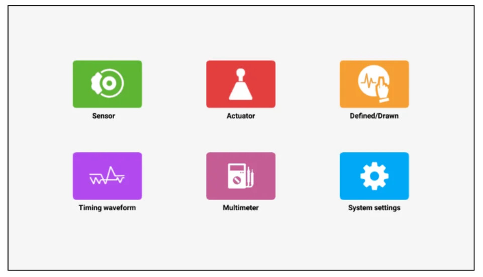
- S2-2 Sensorbox is specially developed for diagnosing/simulating sensor faults. It mainly includes “Sensor”, “ Actuator”, “Defined/Drawn”, “Timing Waveform“ and “ multimeter”.
Launch Sensor S2-2 2 box Features
- Contains an integrated library of standard waveforms
- One click to enters the intuitive menu of sensor, actuator, defined/drawn the waveform, timing waveform, multimeter, system settings.
- Simulate working condition of sensors without replacing parts
Throttle & Pedal Sensor
Airflow Meters
Oxygen Sensor
Temperature Sensor
EGR Sensor
Injectors Sensor
Crank
Cam sensors inductive & hall
Compatible with DBScar VII Device
- X431 deice: X431 pro 5, PRO3S+ V5.0, V+, X431 Pro3 APEX, X431 PRO5, PRO DYNO, PROS V5.0, X431 PRO TT, X431 V+ 5.0 (PRO3), Pro3 ACE, X431 PRO ELITE, PRO3S+ SmartLink HD, PRO3 V+ Elite, X-431 PAD III V2.0 and PAD VII
- IMMO Series: IMMO Plus, IMMO Elite,
- PAD Series: PAD VII Elite ,PAD V Elite,
- Creader Series: CRP919X BT, CRP919E BT
Defined
- Waveform: There are 9 waveforms to choose; Forward sine wave, reverse sine wave, forward square wave, reverse square wave, medium voltage, straight line, high / low voltage straight line, triangle wave, and trapezoidal wave.
- Frequency: Set the frequency of the selected waveform.
- Amplitude: Set the amplitude of the selected waveform.
- Offset: Set the offset of the selected waveform.
- Phase: Set the phase of the selected waveform.
- Duty cycle: Set the duty cycle of the selected waveform.
- Signal sync: Can cause CH1 and CH2 to output signals at the same time.
Hand-drawn
- Total frame: 1-3 (optional). Indicate the total number of output points
- Generally, one waveform is composed of 100 points. The values 1-3 indicate that you can select 100, 200, or 300 points to form a waveform.
- Edit frame: You can edit a single frame or edit all
- Waveform: You can select a preset waveform and place it in the hand-drawing area
- Frequency: Frequency of a single frame (for 3-frame output, the total frequency is the set frequency/3)
- Amplitude: Amplitude of the output waveform
- Offset: Offset of the output waveform
Launch S2-2 SensorBox Functions:
Actuator: Is used to simulate the output control signal of automobile electronic control system, so as to judge the working conditions of automobile actuators such as idle motor, EGR solenoid valve, etc.
Multimeter: Through this function, users can test voltage, resistance, and capacitance.
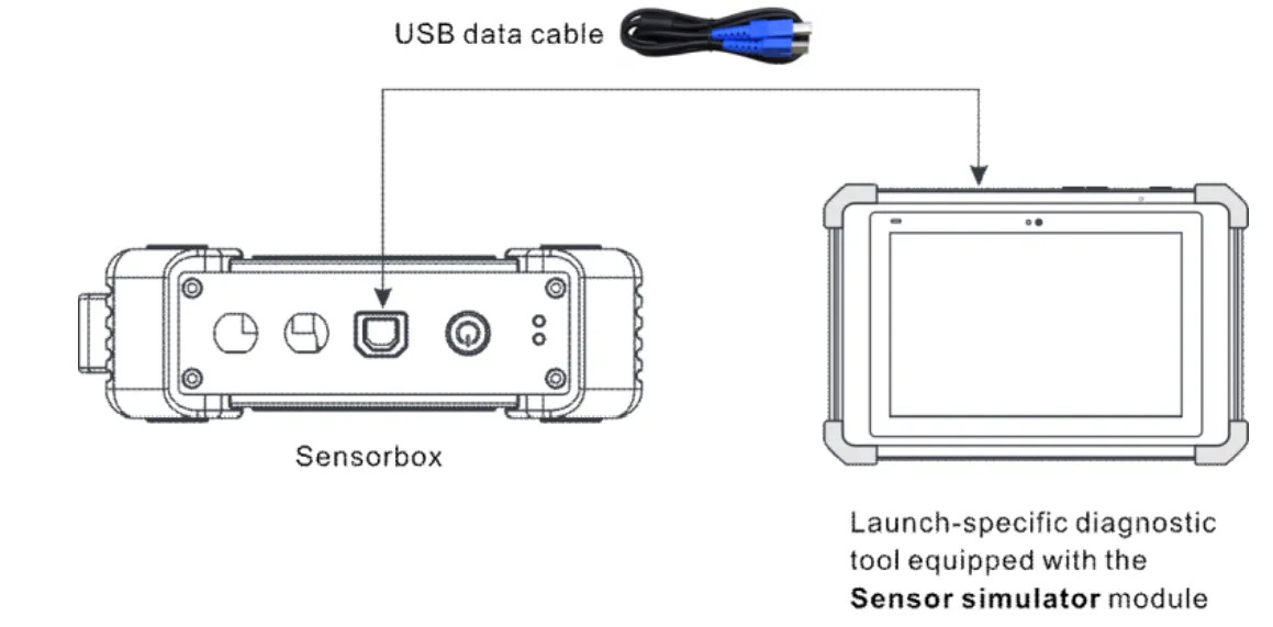
How to Connect S2-2 Sensorbox
1) Insert one end (B-type terminal) of the USB cable into the B-type USB port of the sensor module host, and then insert the other end into the USB port of the diagnostic tool.
2) Press and hold the power button for over 3s to start the sensor module. If the electric quantity is normal, the green lamp is steady on.Indicator lamp status description:
Green lamp:
-
Steady on: normal electric quantity
-
Flashing at an intermediate speed: low electric quantity (regardless of whether red lamp flashes)
-
Flashing at a low speed: charging in progress
Red lamp:
-
Steady on: diagnostic tool connected
-
Flashing: diagnostic tool disconnected. It will enter the charging status only when the red lamp is flashing. The green lamp is flashing at a low speed during charging.
3) Start the diagnostic tool and access the toolbox. Tap Sensor Simulator to access the job menu of sensor.
Job Menu
The sensor module is mainly divided into five functional modules
1) Sensor: Use output voltage or waveform to simulate the working status of the on-board sensor, so as to accurately judge the quality of the sensor and reduce blind replacement of accessories.
2) Actuator: Used to output PWM signal to drive the on-board coil actuator.
3) Defined/Drawn: Users can customize sensor waveforms to facilitate future sensor signal simulation.
4) Timing waveform: Customize timing waveform to match the engine (crankshaft + camshaft), and output in the same phase.
5) Multimeter: universal multimeter functions.
LAUNCH X431 S2-2 SensorBox Operation Guide:
Provide sensor voltage to operate & test actuator injector, VVT actuator, solenoid valve.
Operation:
Follow the connection images to connect S2-2 SensorBox and the vehicle correctly
Insert the USB Cable in the S2-2 SensorBox package into Launch X431 Tool (i.e. X431 PAD V)
It will show “USB device connected successfully” once the USB cable is inserted.
Then select Actuator>> VVT solenoid valve
- Function 2: Simulate sensor waveform for ECU
Troubleshoot the car without replacing the sensor.
Easy to check ABS speed sensor, crank & cam sensor, Temp sensor…
Operation:
Follow the connection images to connect S2-2 SensorBox and the vehicle correctly
- Function 3: Multimeter
Allow you to troubleshoot with 1 tool
Operation:
Connect S2-2 SensorBox and X431 tool, and connect the multimeter test pens to S2-2 SensorBox
Through this function, users can test voltage, resistance, and capacitance.
X-431 S2-2 TECHNICAL PARAMETERS
| Parameter | Range |
| Number of channels | 2 |
| Precision | 1 % |
| Amplitude range | 0~20V |
| Max output current | 20mA |
| Predefined frequency range | 0 – 20 kHz |
| Square wave signal pulse frequency | 0~15KHz |
| Square wave signal duty cycle | 0~100% |
| Power supply | Simulator sensor output/max current 20mA (output is powered by battery) – Drive solenoid, ignition coil/output current 2A (external power supply) |
| USB | USB2.0 Type B (with charging and power supply function/5V) |
| DC Voltage simulation | Support |
| Fixed Frequency simulation | Support |
| Predefined waveform simulation | Support |
| Hand-drawn waveform simulation | Support |
| Signal generator interface | 2 |
| External power supply port | 1 |
| Solenoid interface | 1 |
| Multimeter interface | 2 |
| Operating temperature range | 0℃~50℃ |
| Storage temperature range | -30℃~70℃ |
| Certificate | CE, FCC, RoHS |
Multimeter:
| Parameter | Range |
| DC voltage | 0 V – 700 V |
| AC voltage | 0 V – 700 V |
| Resistance | 0 Ω – 40 MΩ |
| Capacitance | 0 F – 100 µF (maximum 30 s measurement time) |
| Diode | 0 V – 1,5 V |
| Continuity detection | Sounds below 30 Ω |
Package Includes
1pc x Sensor module
2pcs x HT30 test leads
1pc x 7-pin interface adapter cable
1pc x Battery clamps cable
1pc x USB cable
3pcs x 6-way breakout lead
2pcs x Multimeter test pen (black + red - )
5pcs x Colored 4mm female probes
20pcs x Needles
1pc x Power adaptor
2pcs x Screw heads
1pc x User manual
1pc x Packing list
1pc x Box


 Whatsapp: +86-13480885545
  Live Support: Chat with us online
 Email: 8081242@qq.com
 Skype: jensen.tce


 Skype: jensen.tce
  Live Support: Chat with us online


